Installation in the LI-7550
The procedure described here is for the retrofit installation. Prior to the installation, update the LI-7500A/RS or LI-7200/RS embedded and PC software. See Software Updates for Gas Analyzers for details.
1. Install the SmartFlux Module
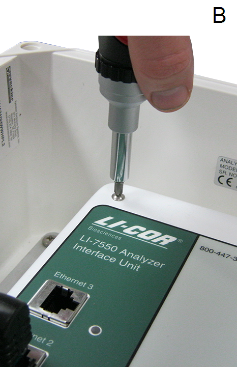
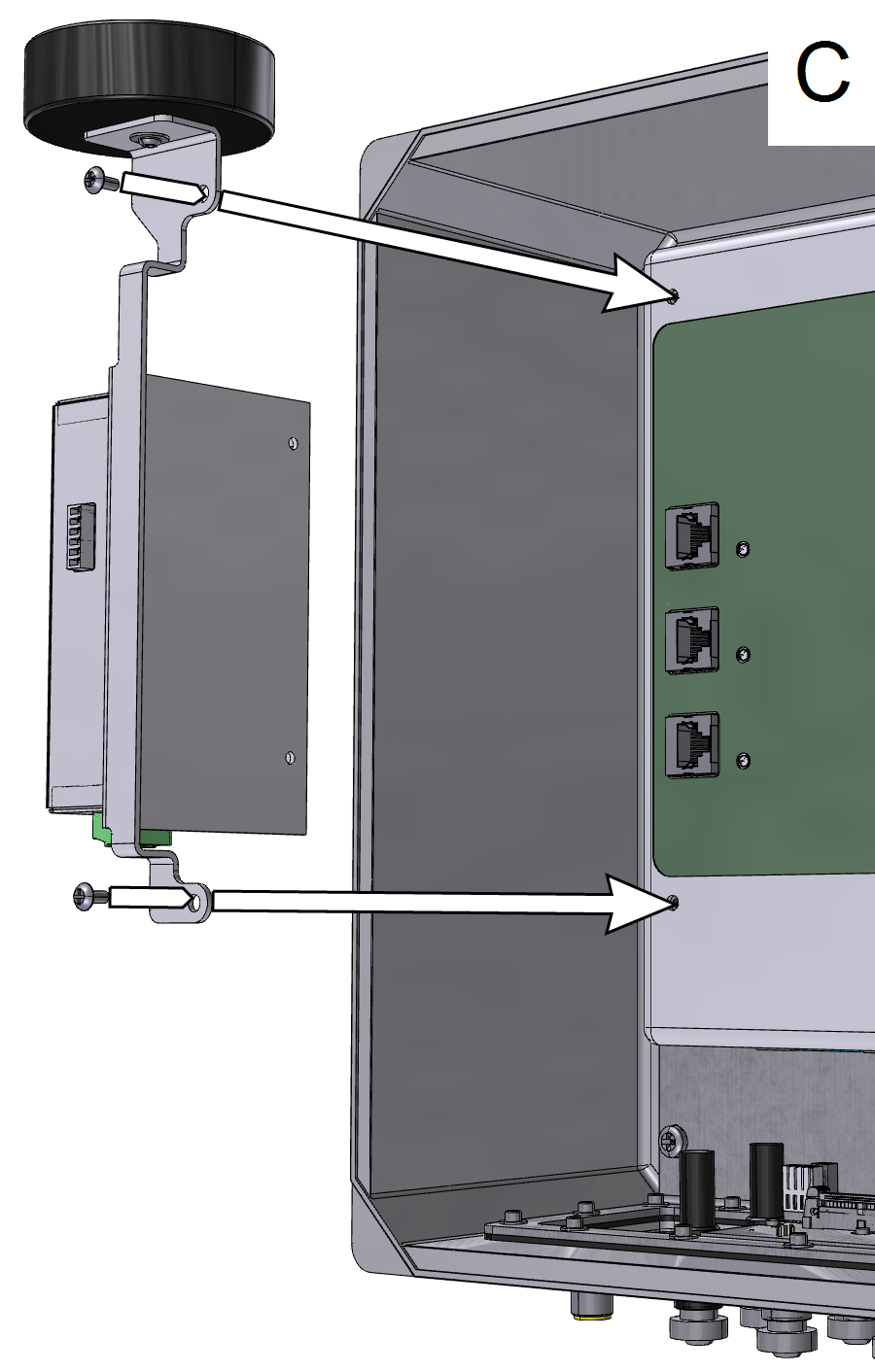
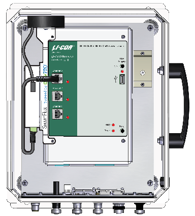
Stop datalogging and power off the analyzer. Inside the LI-7550, unplug the Ethernet cables from the Ethernet ports, and remove the left two screws that secure the faceplate. Install the SmartFlux System as shown in Figure B‑1 (C).
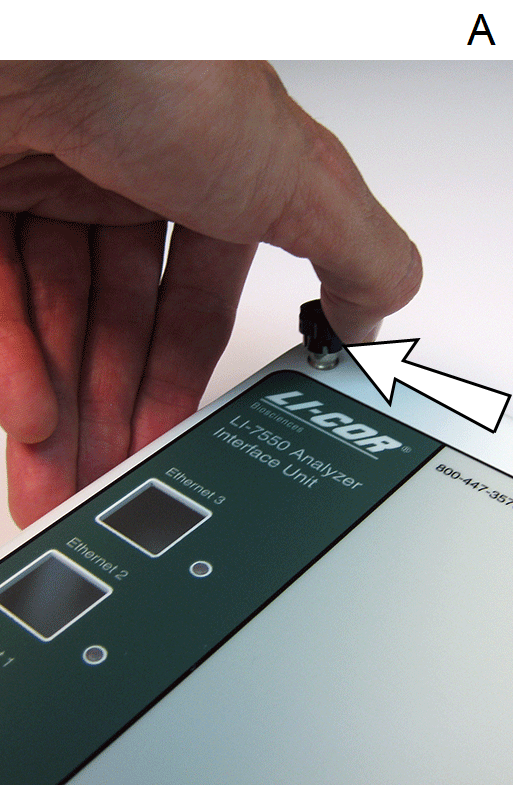
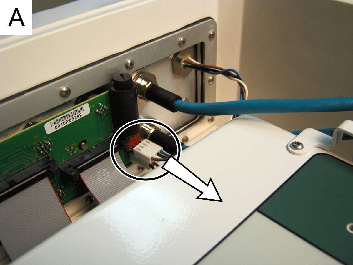
Note: On early units the faceplate is secured with hex thumb screws. The left two thumb screws should be removed and replaced with screws included with SmartFlux System. Completely loosen the left two thumb screws and press hard against the side of the screw, as shown below (A), and the screw will pop off.
2. Install the Power Wiring Harness
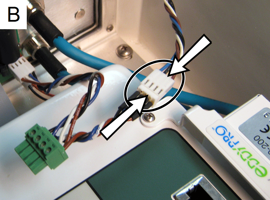
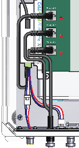
First, remove the power terminal from the circuit board at the bottom of the LI-7550 (A in Figure B‑2). It has four leads - brown, white, blue, and black. Install the power wiring harness (B, C) and attach the terminal to the SmartFlux System as shown (D).

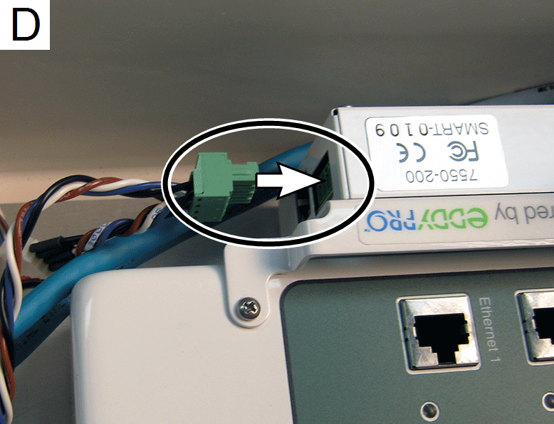
Install the straight RJ45 terminal of the 30 cm (12 in.) Ethernet cable into the data terminal at the bottom of the SmartFlux unit. Install the 90° RJ45 connector into any one of the LI-7550 Ethernet ports.
Reinstall the other Ethernet cables that were removed during the installation, as shown in Figure B‑3.
The hardware installation is now complete. You can connect the power cable to power up the system.