What's new in the LI-8250 Multiplexer?
LI-8250 Multiplexer firmware version 2.2.0 adds support for 8200-105/C Automated Canopy Chambers.
8200-105 and 8200-105C Automated Canopy Chambers function like 8200-104 and 8200-104C Long-term Soil Chambers, but offer a much larger volume. Automated Canopy Chambers support Net Ecosystem Exchange measurements (NEE).

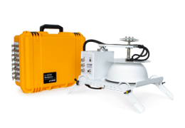
8200-105/C Automated Canopy Chambers
Automated Canopy Chambers provide a large area and volume and are optimized for measuring plant-mediated fluxes, greenhouse gas (GHG) fluxes, Net Ecosystem Exchange (NEE) measurements, and a range of measurements that require a large volume or area. Automated Canopy Chambers are compatible with the LI-8250 Multiplexer (firmware v2.2.0 or higher required) and a variety of gas analyzers (LI-COR gas analyzers recommended). The height of 8200-105 and 8200-105C chambers can be extended up to 135 cm with base extensions. Automated Canopy Chambers are also compatible with 8250-01 Extension Manifold, 8250-02 Calibration Manifold, and in combination with LI-COR chambers and other chamber options.
-
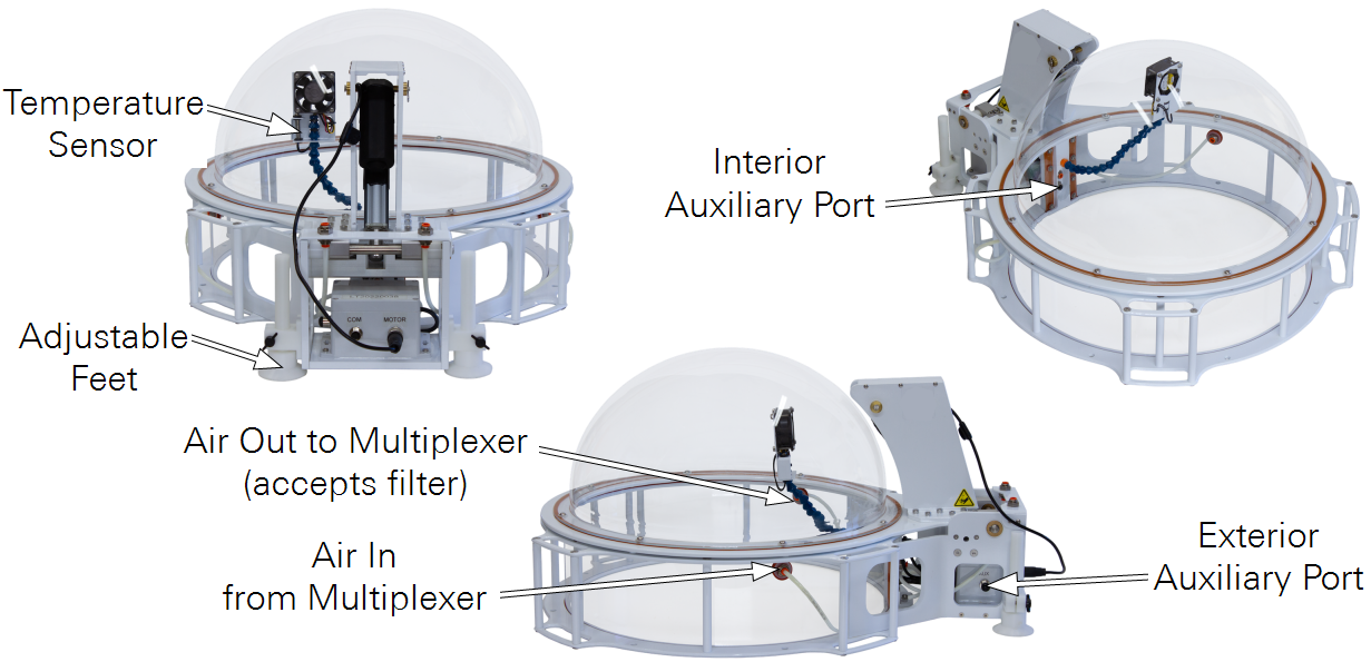
Temperature Sensor: Attached to the arm that also supports the fan.
-
Adjustable Feet: Two feet can be adjusted to stabilize the chamber.
-
Interior Auxiliary Port: Hosts a sensor inside of the chamber. Supports analog (voltage or current) and SDI-12.
-
Exterior Auxiliary Port: Hosts a sensor outside of the chamber. Supports analog (voltage or current) and SDI-12.
-
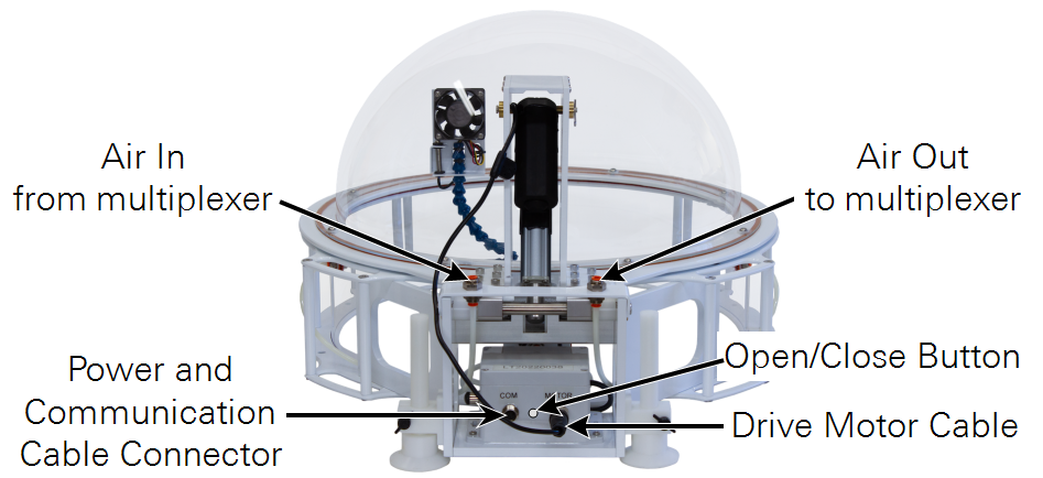
Air Out to Multiplexer: Carries sample air to the multiplexer and gas analyzer. The filter is to be installed on this port (see Figure 1‑5).
-
Air In from Multiplexer: Returns air after measurement.
8200-105/C Chambers are equipped with a built-in temperature sensor and two auxiliary sensor ports—one inside and one outside the chamber. Data from these ports are recorded when a measurement is made, allowing ancillary data to be recorded with soil flux datasets. Ports support analog current for LI-190R or LI-200R sensors and digital (SDI-12) data for soil probes. Each Automated Canopy Chamber occupies a single port on the multiplexer or extension manifold.
Each Automated Canopy Chamber includes a 10-cm tall soil collar. A 20-cm collar and base extensions (Table 1‑1) are available as options.
Field deployment tutorial
The following tutorial guides you through the steps of a field deployment. Be sure you have done everything in the Initial setup in the instruction manual before starting this tutorial.
Sample location should be representative of the site. Avoid choosing locations that will bias the measurements. Do not install the chamber over areas of standing water or hollows where flooding is a possibility. For the best results, choose a flat soil surface to deploy the chamber. Remove large debris from the soil surface, if needed.
-
Each chamber includes a collar that is installed upside-down on the inside of the chamber and secured with zip ties for shipping.
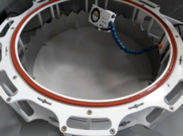
Figure 1‑3. The collar is installed upside-down inside the chamber for shipping. With the serrated edge down, press the collar into the soil. If soil is dense, you may need to cut a circle for the collar using a trowel or spade.
-
Install the base extension (optional).
-
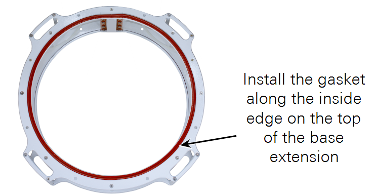
Install the gasket on the side that will be the top of the base extension.
The gasket has an adhesive strip on one side. Remove the cover from the adhesive strip and apply the gasket along the inside edge of the extension.
-
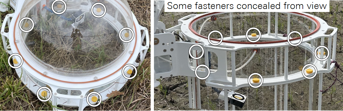
Attach the base extension to the collar with the yellow-capped bolts from the base extension accessories.
-
-
Determine the ideal chamber orientation.
Orient the chamber so the drive mechanism is away from the sun at solar noon to prevent the chamber mechanism from shading the sample area.

Figure 1‑4. Orient the chamber so shadows are cast away from the sample area. -
Attach the chamber to the collar or base extension.
Secure the chamber with the yellow-capped bolts from the chamber accessories (see Figure 1‑7). Be careful not to crossthread the fasteners and tighten by hand only until snug.
-
Adjust the feet to stabilize the chamber.
Two adjustable feet can be extended to stabilize the chamber. Extend them to so the chamber does not rock on the collar. Be sure the chamber is stable in both the open and closed position.
-
Install the filter on the intake tube in the chamber.
Each chamber includes a filter in the accessories bag. The filter is to prevent particles or liquid water from entering the tubing. It should be installed inside the chamber on the port that delivers gas to the multiplexer.

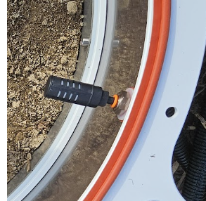
Figure 1‑5. The filter is to be installed on the tube that goes to the multiplexer. -
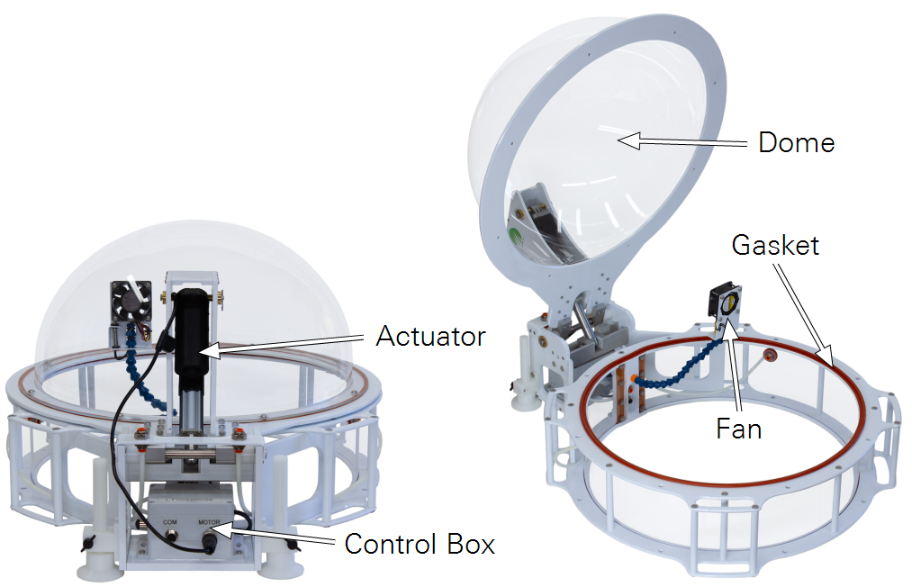
Adjust the position of the fan and air temperature sensor.
The fan should move air around the chamber, but not blow directly onto or away from the soil surface. It should be positioned so that the air temperature sensor is shaded, and not under direct solar load. See Figure 1‑4.
-
Connect the chamber drive cable, tubes, and power/data cable.
The drive motor cable connects to the connector on the chamber (MOTOR). The chamber connects to the LI-8250 or 8250-01 Extension Manifold with a standard cable/tube bundle (9982-056).
-
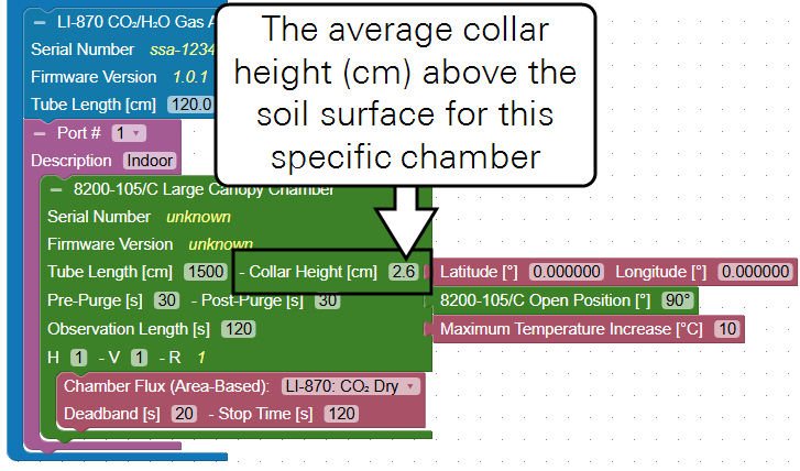
Measure the collar height.
Measure the offset between the soil surface and the top of the collar and enter it in the chamber block on the Configuration page. If the chamber has a base extension, add the extension height to the collar height.

Figure 1‑6. Automated Canopy Chamber collar offset is the distance between the surface and the upper plate of the collar. The minimum offset is 2.57 cm due to the height of the acrylic base. 
Figure 1‑7. Base extensions should be added to the collar height. -
Enter the collar height including base extensions into the chamber block on the Configuration page.
Each chamber block added to the system requires the collar height parameter.
-
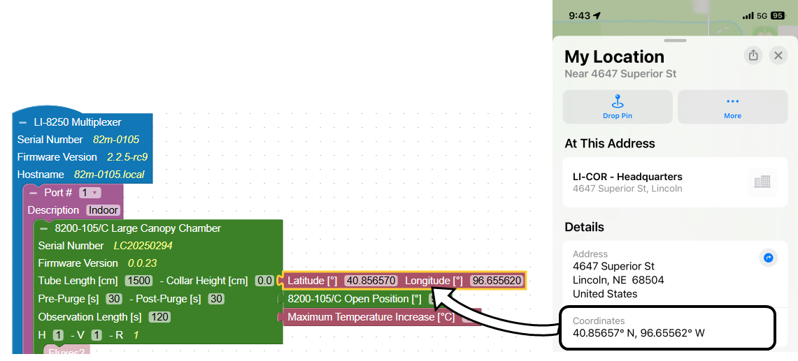
Enter the precise location of each collar (optional).
A smart phone may be able to provide precise GPS coordinates for individual chambers using a map application. After noting the location, you can enter the information in the interface.
-
Be sure there is sufficient clearance for the chamber to move to the open position. The default open position is <90° up from the closed position, but three other open positions (Figure 1‑8) are available to avoid terrain or obstructions that interfere with the movement. Chamber open positions are set for each individual chamber in the software Configuration tab with the Open Position block.

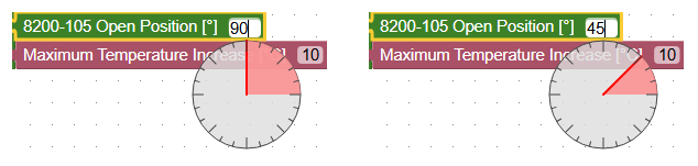
Figure 1‑8. Chamber open positions (top) are set in the software (bottom). -
Set the Maximum Temperature Increase.
Each chambers has an option to cancel the measurement and open the chamber if the temperature inside the chamber rises above starting temperature by a set amount. This setting is to prevent overheating the sample. The ideal setting depends on the site and chamber, but 3 or 5 ° C is a good starting place.
-
Connect and configure ancillary sensors.
This step can be completed when you are preparing for field deployment or while you are in the field. If you skipped or partially completed it earlier, be sure to finish.
Software features
Several new software features are added for the new chambers.
Automated Canopy Chamber blocks
8200-105/C Automated Canopy Chambers have a specific block. Choose the appropriate block for your chamber.
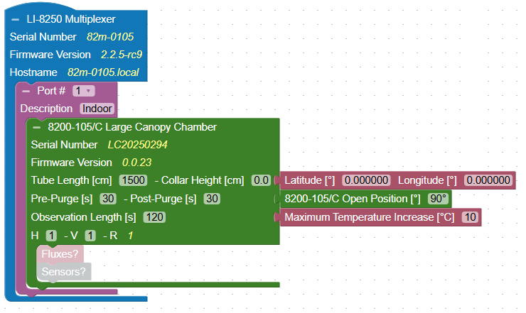
- Displays: The serial number and firmware version of the chamber.
- Fits into: A Port block.
- Requires: One or more Flux blocks, Tube Length (use default settings unless altered), Collar Height (measured at the site), Pre-Purge, Post-Purge, Observation Length, and H and V.
- Accepts: Sensor blocks for light sensors, soil probes, or other sensors (optional), Location block (optional), Open Position block (optional), and Maximum Temperature Increase block (recommended).
Maximum Temperature Increase block
All chambers have an option to cancel the measurement and open the chamber if the internal chamber increases by a user-settable amount during the measurement. This can prevent overheating the sample while the chamber is closed.

- Fits into: A Chamber block.
- Allows: A threshold representing the maximum temperature change (°C) to allow before canceling a measurement and opening the chamber.
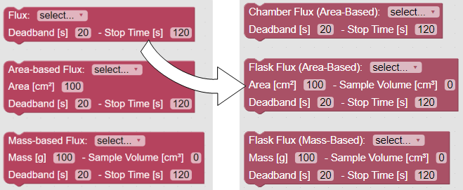
Terminology updates
Math > Flux blocks are identified by the type of flux - mass or area. Reverts a previous change to reduce confusion.
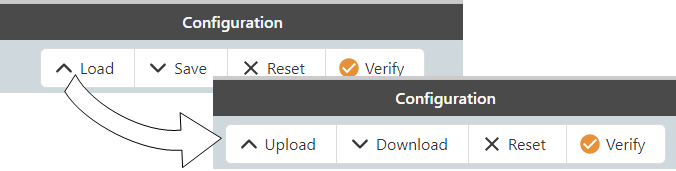
Configuration Editor
Earlier versions presented four options in the configuration editor. These have been extended to accommodate other changes to the interface and device.
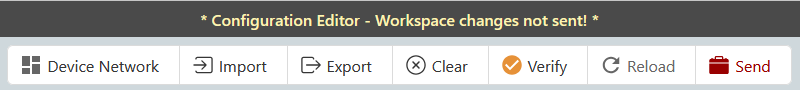
In earlier firmware versions, the interface, which is displayed in a web browser, was continuously synchronized with the LI-8250. Changes were applied to the LI-8250 immediately. Now, the configuration is no longer synchronized with the interface. Instead, the browser loads a copy of the configuration for editing. If you make changes, you must apply those changes by clicking Send. The configuration editor warns you with a conspicuous message: Workspace changes not sent.
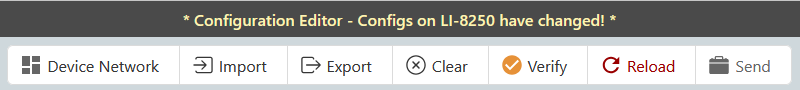
If another user loads a new configuration to an LI-8250 while you are viewing the configuration, a different message alerts you: Configs on LI-8250 have changed.
If you have changed the configuration locally and another user applies changes, a combined message alerts you. In this case, you might need to correspond with your peers to ensure you configure the system as desired.
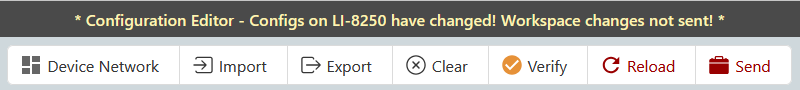
The Configuration Editor presents options to edit and manage the configuration.
-
Device Network: Click to view a schematic of devices connected to the system. This is allows you to view schematic without returning to the home screen.
-
Import: Load a configuration file from your computer into the workspace.
-
Export: Saves the current configuration to the Downloads folder on your computer.
-
Clear: Resets the work space; clears any blocks and settings.
-
Verify: Checks and reports missing or incorrect information in the configuration.
-
 The configuration is complete and valid. All systems go.
 -
 There may be something missing from your configuration but the sampling sequence will still run.
 -
 The configuration is invalid. The configuration will not be remembered by the multiplexer if you navigate away from the configuration page. The sampling sequence will not run. However, you can save the configuration to your computer for editing at a later time.
-
-
Reload: Reloads the LI-8250 configuration into the workspace.
-
Send: Sends the configuration to the connected LI-8250.