Automated Canopy Chambers
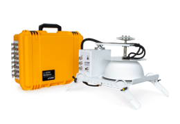
Automated Canopy Chambers provide a large area and volume and are optimized for measuring plant-mediated fluxes, greenhouse gas (GHG) fluxes, Net Ecosystem Exchange (NEE) measurements, and a range of measurements that require a large volume or area. Automated Canopy Chambers are compatible with the LI-8250 Multiplexer (firmware v2.2.0 or higher required) and a variety of gas analyzers (LI-COR gas analyzers recommended). The height of 8200-105 and 8200-105C chambers can be extended up to 135 cm with base extensions. Automated Canopy Chambers are also compatible with 8250-01 Extension Manifold, 8250-02 Calibration Manifold, and in combination with LI-COR chambers and other chamber options.
-
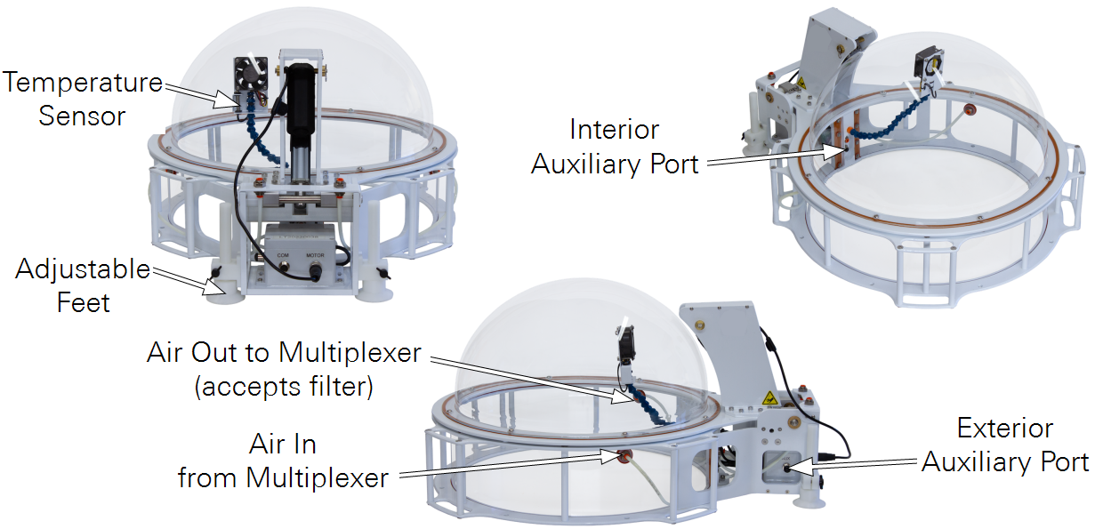
Temperature Sensor: Attached to the arm that also supports the fan.
-
Adjustable Feet: Two feet can be adjusted to stabilize the chamber.
-
Interior Auxiliary Port: Hosts a sensor inside of the chamber. Supports analog (voltage or current) and SDI-12.
-
Exterior Auxiliary Port: Hosts a sensor outside of the chamber. Supports analog (voltage or current) and SDI-12.
-
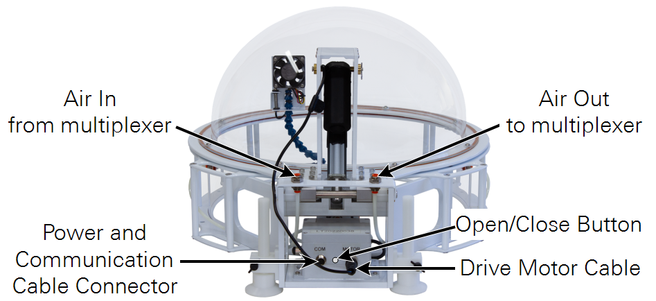
Air to Multiplexer: Carries sample air to the multiplexer and gas analyzer. The filter is to be installed on this port (see Figure 3‑8).
-
Air from Multiplexer: Returns air after measurement.
8200-105/C Chambers are equipped with temperature and pressure sensors, and two auxiliary ports. One is inside the chamber; the other is outside the chamber. Data from these ports are recorded when a measurement is made, allowing ancillary data to be recorded with soil flux datasets. Ports support analog (voltage or converted current) or digital (SDI-12) data.
Installing Automated Canopy Chambers
Each Automated Canopy Chamber occupies a single port on the multiplexer or extension manifold.
-
Each chamber includes a collar that is installed upside-down on the inside of the chamber and secured with zip ties for shipping. With the serrated edge down, press the collar into the soil. If soil is dense, you may need to cut a circle for the collar using a trowel or spade.
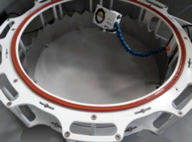
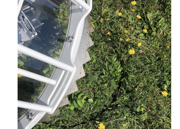
Figure 3‑6. The collar is installed upside-down inside the chamber for shipping. -
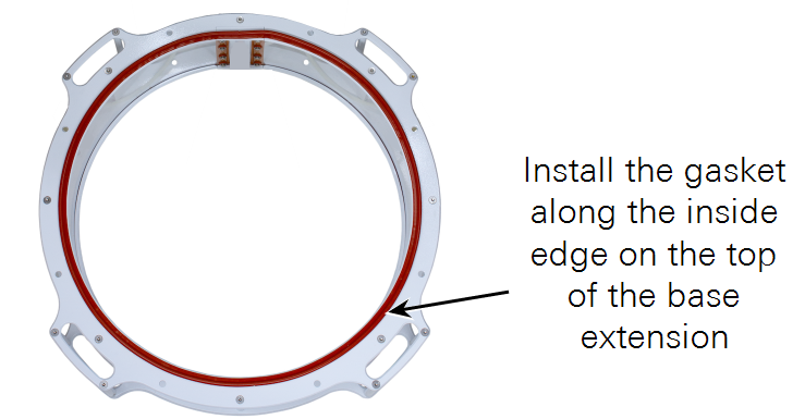
Install the base extension (optional).
Install the gasket on the side that will be the top of the base extension. Expose the adhesive and apply the gasket along the perimeter of the base extension.
-
Determine the ideal chamber orientation.
Orient the chamber so the drive mechanism is away from the sun at solar noon to prevent the chamber mechanism from shading the sample area.

-
Attach the chamber to the collar or base extension.
Secure the chamber using eight yellow-capped bolts from the chamber accessories (see Figure 3‑7). Be careful not to cross-thread the fasteners and tighten by hand only until snug.
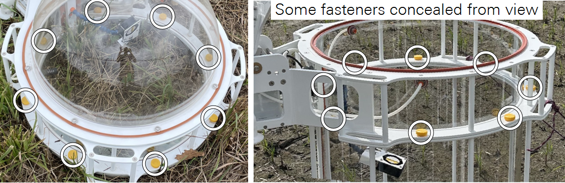
Figure 3‑7. Chambers, extensions, and collars are connected with eight bolts each. -
Adjust the feet to stabilize the chamber.
Two adjustable feet can be extended to stabilize the chamber. Extend them to so the chamber does not rock on the collar. Be sure the chamber is stable in both the open and closed position. You may need to stabilize tall chambers with guy wires and stakes.
-
Install the muffler on the air-out tube from the chamber.
Each chamber includes a gas muffler in the accessories bag. The muffler is to prevent particles or liquid water from entering the tubing. The muffler should be installed inside the chamber on the port delivers gas to the multiplexer.

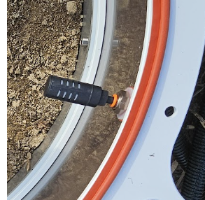
Figure 3‑8. The gas muffler is to be installed on the tube that goes to the multiplexer. -
Adjust the position of the fan and air temperature sensor.
The fan should move air around the chamber, but not blow directly onto or away from the soil surface. With a base extension, the fan should be positioned toward the middle of the base extension for optimal mixing. It should be positioned so that the air temperature sensor is shaded and not under direct solar load. See Figure 3‑8.
-
Connect the chamber drive cable, tubes, and power/data cable.
The drive motor cable connects to the connector on the chamber (MOTOR). The chamber connects to the LI-8250 or 8250-01 Extension Manifold with a standard cable/tube bundle (9982-056).
-
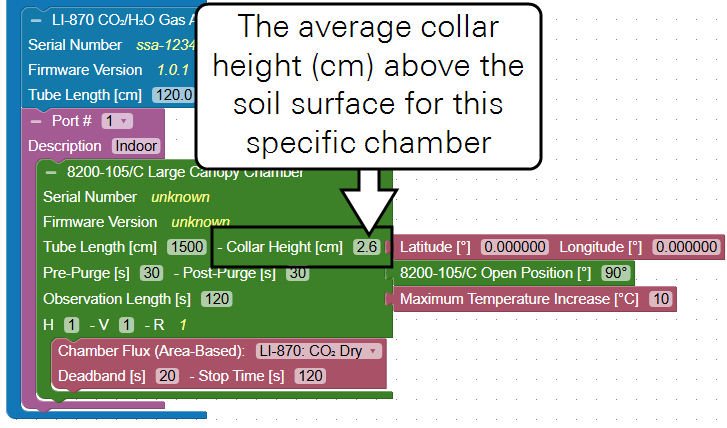
Measure the collar height.
Measure the offset between the soil surface and the top of the collar and enter it in the chamber block on the Configuration page. If the chamber has a base extension, add the extension height to the collar height.

Figure 3‑9. Automated Canopy Chamber collar offset is the distance between the surface and the upper plate of the collar. The minimum offset is 2.57 cm. 
Figure 3‑10. Base extensions should be added to the collar height. -
Enter the collar height including base extensions into the chamber block on the Configuration page.
Each chamber block added to the system requires the collar height parameter.
-
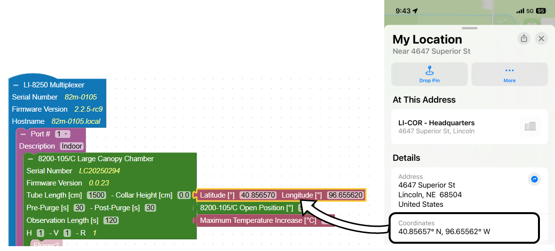
Enter the precise location of each collar (optional).
A smart phone may be able to provide precise GPS coordinates for individual chambers using a map application. After noting the location, you can enter the information in the interface.
-
Be sure there is sufficient clearance for the chamber to move to the open position. The default open position is <90° up from the closed position, but three other open positions (Figure 3‑11) are available to avoid terrain or obstructions that interfere with the movement. Chamber open positions are set for each individual chamber in the software Configuration tab with the Open Position block.

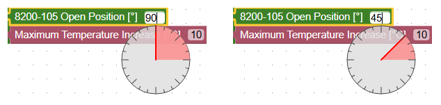
Figure 3‑11. Chamber open positions (top) are set in the software (bottom). -
Set the Maximum Temperature Increase.
Each chambers has an option to cancel the measurement and open the chamber if the temperature inside the chamber rises above starting temperature by a set amount. This setting is to prevent overheating the sample. The ideal setting depends on the site and chamber, but 3 or 5 °C is a good starting place.
-
Connect and configure ancillary sensors.
This step can be completed when you are preparing for field deployment or while you are in the field. If you skipped or partially completed it earlier, be sure to finish. If you've already done it, skip ahead. See Using sensors with chambers for details.
Parking the chamber - preparing for transportation
When moving the chamber, be sure that the bowl is in the closed position. Press the Open/Close button to close the chamber. Disconnect the power/data cable and then remove the chamber from its collar by removing the bolts. Invert the collar and re-combine the chamber and collar. This will help protect the chamber and mechanism from damage while in transit.
Caution: Be sure to park the chamber before moving it, performing maintenance, or placing it in storage. Handling the chamber while it is not parked can damage the chamber.