Maintenance
The section describes maintenance procedures for the gas analyzer and components.
Instrument checkup schedule
A good site maintenance plan will help ensure more complete data coverage. These recommendations are preventive maintenance—follow them to prevent issues.
| Frequency | Check... |
|---|---|
| When you first deploy the instrument: | |
|
Check the signal strength and record this for a baseline. This will help you determine when the optics should be cleaned. |
|
| Every day or every few days: | |
|
Check the overall performance of the instruments, including the measured values and diagnostic information. This will ensure that you don't lose data (or that you lose less data) if something is wrong. |
|
|
Check the measured values. Air temperature, pressure, sonic temperature, dew point, gas concentrations, covariances and fluxes. Any unexpected readings may indicate an issue. |
|
|
Check the diagnostics. Signal strength, detector temperature, chopper housing temperature, and thermocouples. |
|
| Once per week: | |
|
After installing the new system, start by checking the signal strength once per week. There is no absolute guideline for good or bad signal strength, but 100% indicates very clean optics and optimal performance from the analyzer. If the signal strength has dropped, it is a good idea to clean the optics. For most sites, the maintenance frequency is once every 3-4 weeks. The signal strength limit, below which the instrument readings are compromised, varies due to the spectral characteristics of the contaminants involved. Typically, signal strength values should be maintained in the upper 90’s for consistent performance. |
|
| Once per month: | |
|
Check the zero and span. As you become familiar with your instrument, you will probably find that this does not need to be checked as often. |
|
|
Clean the upper and lower windows of the analyzer. |
|
|
Download all your data and store it to an archive. |
|
|
Check cables for damage. Tighten any loose cable connections. |
|
| Every six months: | |
|
For installations in humid environments, replace the head chemicals every six months. |
|
| Once per year: | |
|
Replace the head chemicals. For most installations annual replacement is sufficient. |
|
| Every two years: | |
|
Check the instrument calibration with one or more span gases. If it is outside the specifications, return the instrument to LI-COR for recalibration. |
|
Cleaning the gas analyzer optical path
Caution: Power off the gas analyzer (disable the power supply or disconnect the power cable) before conducting any maintenance that involves disassembly or disconnecting cables. Disassembling the instrument or detaching or attaching head cables while the instrument is powered on may damage the instrument or result in a loss of data.
The upper and lower optical windows should be cleaned when necessary (visible dirt or stains, or smaller than expected CO2 Signal Strength).

The windows are sapphire, and are extremely durable and resistant to scratches; clean the windows with any mild detergent or glass cleaner. Also, coating the windows with a water resistant windshield type coating (such as Rain-X®) or a high quality automobile type wax may help prevent droplets from remaining on the windows during rainstorms. Mounting the sensor head at a 10 to 15° angle from vertical will help prevent water from pooling on the window (see Figure 9‑1 ).
Changing the SmartFlux Core System fuses
Power for the SmartFlux Core System and the pass-through power supply are protected by fuses. This section describes how to replace a blown fuse. Pass-through power flows through the SmartFlux Core System to pins on ports 1, 2 and 3 to power a connected sonic anemometer. To change the fuses, power off the SmartFlux Core System. Remove the power and data terminal strips. Remove the six screws on the side of the case and remove the case lid.

Caution: Do not damage nearby electronic components when removing fuses. Avoid prying on or applying pressure to board-mounted components.
3.0 Amp fuse for pass-through power

The SmartFlux Core System uses two 3.0 A fuses between the Power IN connector and the serial ports (see Figure 9‑2). One of these fuses is for the power wire to the anemometer or other connected device. The other 3.0 A fuse is for the power return wire and protects the system in case problems such as improper grounding cause a power surge.
If the SmartFlux Core System boots up and has power, but the Power OUT LED does not light up, it is likely that one of the two 3.0 A fuses has failed.
- Measure both 3.0 A fuses with an ohmmeter. If one of them is an open circuit, replace it with the spare 3.0 A fuse.
- Remove the failed fuse and the spare 3.0 A fuse by gently prying under each fuse with a small flat-bladed screwdriver.
- Gently press the good (spare) fuse into the fuse holder. If both 3.0 A fuses are blown, you will need to order another 3.0 A fuse (part number 348-16020).
- Replace the lid and six screws on the SmartFlux Core case.
Note: A blown 3.0 A fuse usually indicates a wiring problem between the SmartFlux Core System and the sonic anemometer or other connected device. Check for proper system grounding and remove possible causes of a short circuit in the power cable for the connected device. Also, while this fuse is rated at 3.0 A, keeping power use at 2.0 A or less will ensure a nearly unlimited lifetime for the fuse.
1.0 Amp fuse
If the Power OUT LED lights up, but the Power IN LED does not light up, it is likely that the 1.0 A fuse has failed (see Figure 9‑2).
- Measure the 1.0 A fuse with an ohmmeter. If it is an open circuit, replace it with the spare 1.0 A fuse (part number 348-13880).
- Remove the failed fuse and the spare 1.0 A fuse by gently prying under each fuse with a small flat-bladed screwdriver.
- Gently press the good (spare) fuse into the fuse holder.
- Replace the lid and six screws on the SmartFlux case.
Note: A blown 1.0 A fuse may indicate a problem with the SmartFlux Core System. If the spare 1.0 A fuse also fails when installed, contact LI-COR support.
Replacing the internal chemicals
Caution: Power off the gas analyzer (disable the power supply or disconnect the power cable) before conducting any maintenance that involves disassembly or disconnecting cables. Disassembling the instrument or detaching or attaching head cables while the instrument is powered on may damage the instrument or result in a loss of data.
There are two small plastic bottles, each containing Ascarite II and magnesium perchlorate, in the analyzer housing that keep the optics free of CO2 and water vapor. These bottles should be replaced annually (or every 6 months in hot, humid climates). Replacement bottles are available from LI-COR in sets of two (part number 7500-950). If you want to recharge the bottles yourself, you can acquire the of Ascarite II and magnesium perchlorate from another source.
Note: Calibration shifts will occur if CO2 or H2O are not kept out of the analyzer housing.
To change the sensor head scrubber chemicals:
- Remove the chemical bottles.
- The plastic bottles are in the lower analyzer housing in the sensor head. Remove the mounting bracket from the analyzer. Then remove the thumbscrew and thread it into a cap. Pull straight out to remove the plug.

- Remove the lids (with holes) from the old bottles and install the lids on the new bottles.
- The bottles that are to be inserted into the analyzer must have lids with holes to ensure that the air inside the analyzer is scrubbed of CO2 and water vapor.

- Be sure that Teflon membrane is in place to keep the chemicals from spilling.
- Insert the new bottles into the analyzer housing cap first.
- Replace the bottle covers and the cover retention screw and reattach the mounting bracket.
- After installing, allow at least 24 hours (with the instrument powered on) to scrub the housing; otherwise, the instrument may still drift for a time as CO2 and H2O are scrubbed from the analyzer.
- This should be followed by setting the CO2 and H2O zeros. Check the zero again, if possible, after one or two days.

Note: Read the technical note called "Using CO2 and H2O Scrubbers with LI-COR Gas Analyzers" for information about the interactions between scrub chemicals and the air.
See https://licor.app.boxenterprise.net/shared/static/7i418s3uhd2uamoxfmjd.
Software updates
Go to licor.com/support/LI-7500DS/software.html for the latest versions.
We recommend running the most current software at all times including both the embedded and interface software for the LI-7500DS, EddyPro, and embedded software on the SmartFlux Core System.
Embedded instrument software update
To update the embedded instrument software:
- Power up the gas analyzer. Connect your computer using an Ethernet cable.
- Install the LI-7500DS Updater application on your computer.
- Launch the application and select the LI-7500DS from the list.
- Click Update Software.

- The update will take about 5 minutes.
- Caution: Do not close the software, let your PC go to sleep, or power off the instrument during the update process. The software will notify you when the update is complete. If the update fails for any reason, repeat steps 2 and 3.
- After updating the software, check all your instrument configuration settings. The instrument should retain all settings through a software update, but it is always a good idea to make sure everything is set the way you expect.
Updating the win-GHG Windows interface software
To install the Windows interface software for the LI‑7500A/RS, LI‑7200/RS, and LI‑7500DS gas analyzers:
-
Get the latest updater from the link above.
-
Double-click the downloaded file to start the installation wizard.
The updater is named something similar to win-GHG-9.0.0.

-
Follow the steps to install the program.
The software includes WinSCP for file transfer. Be sure to install all components. This application is used to configure the LI‑7500A/RS, LI‑7200/RS, and LI‑7500DS gas analyzers.
The new software has the same basic interactions and workflows as the previous version.
Updating the SmartFlux Core System software
To update the SmartFlux Core System embedded firmware:
-
Get the latest updater and install it on your computer.
Double-click the downloaded file to start the installation wizard.

The file is named smartflux-updater-4.2.1.exe. The installed application is called smartflux-updater.
-
Connect the system to your computer with a network cable.
You can use the cable to connect the SmartFlux Core System directly to your computer or network, or you can connect to the eddy covariance system network switch.
-
Launch the updater, select the unit to update, and then click Update Software....

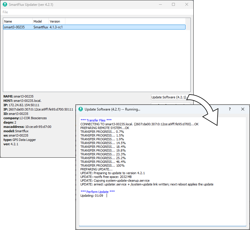
The update will take several minutes to finish. The application will notify you when it is done. Do not turn off the SmartFlux Core System or the computer while the update is in progress.
Note: Serial numbers are not changed by the update. Although the distinction between SmartFlux 2 and 3 Systems is no longer relevant with updated systems, serial numbers will remain intact. For example, a serial number smart3-0235 will not be changed by the update even though the system is now configured as a SmartFlux Core System.
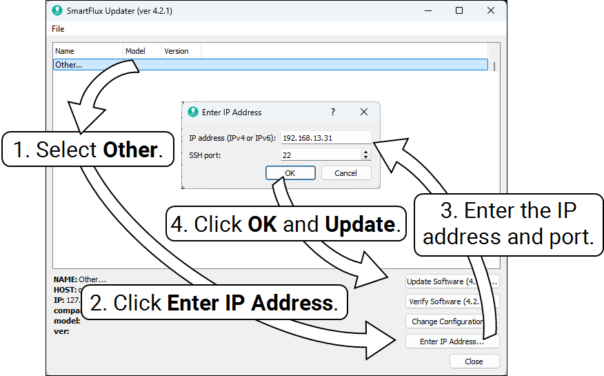
If the SmartFlux 2 or 3 System is on a different local network (for example, it is connected to an RV50X cellular radio), open the updater, click Other..., and then click Enter IP Address. Enter both the IP address of the radio and the port number for the SmartFlux 2 or 3 System. Click OK and then click Update Software.