Registering HOBO RX stations
For HOBO RX stations follow the instructions included with your device. Instructions are also available from onsetcomp.com/resources, where you can search for product information.
Note:
Before you can work with an RX station in LI-COR Cloud, you must perform the hardware setup tasks described in its quick start or user guide. Once your device is set up, register it in LI-COR Cloud:
-
Register the device.
Registering an RX station adds it to your LI-COR Cloud account. Once registered, it appears in your list of devices. If you need to make changes to the RX configuration later, you can. See Devices for details.
-
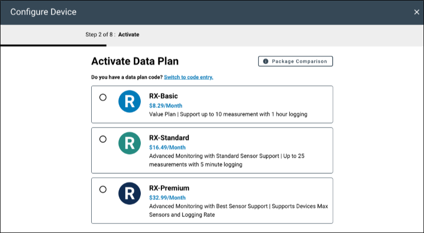
Activate a data plan.
The simplest method is to set up recurring payments with a card.
For registered devices, you can renew or change a data plan at onsetcomp.com/help-center/data-plan-renewals.
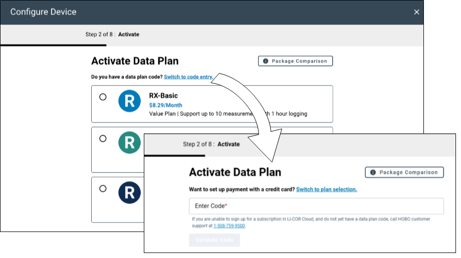
Alternatively, you can call HOBO customer support to purchase a new data plan and Switch to code entry and enter the code that was provided with your order.
-
Specify general configuration settings.
These settings allow you to assign a name, time zone, group, and measurement units. See General configuration.
-
Specify the connection interval.
The connection interval specifies how often the station connects with LI-COR Cloud. Any changes you make in LI-COR Cloud are applied at the time of connection. See Connection interval.
-
Configure sensors.
Sensors are grouped by module and the settings for them differ. Smart sensor logging always appears; others appear only when they are plugged into the station.
-
Set alarms.
Specify settings that register an alarm condition and then specify what action to take when that alarm condition occurs. See Alarms and notifications.
Adding RX stations to the map
Before you can see RX stations on the map, you must add them:
-
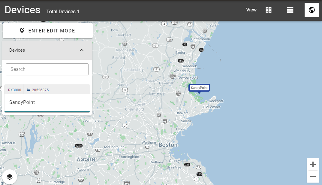
Click Enter Edit Mode.
-
Search the list of devices for the one you want to view on the map.
-
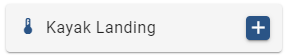
Click the plus sign on the device tile.
-
Click a point on the map to set the position.
-
When you are done adding devices to the map, click Exit Edit Mode.
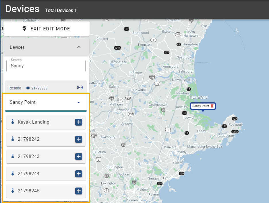
Adding a wireless sensor to the map
Adding a wireless sensor to the map involves a few more steps:
-
Click Enter Edit Mode.
-
Search the list of devices for the station the wireless sensor is connected to.
-
Click the down arrow next to the station name to open a list displaying the wireless sensors connected to the station.
-
Click the plus sign on the device tile.
-
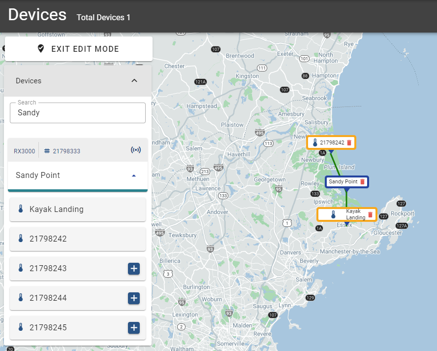
Click a point on the map to set the position.
The map displays lines that indicate the station that hosts the wireless sensors.
-
When you are done adding devices to the map, click Exit Edit Mode.
Removing devices from the map
To remove a device from the map, while in edit mode, click the trash can to the right of its name.

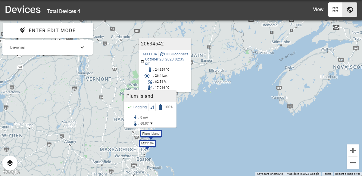
Viewing current device conditions on the map
To view current device conditions:
-
Open the Devices list.
-
Locate the tile of the device you want to view on the map.
You can search the list or scroll through it.
-
Click the device to view the data and information from the device.
Viewing wireless sensor locations
To view the locations of wireless sensors connected to a station:
-
Find the tile for the base station on the map.
-
Click Show Wireless Sensors.
RX station details
The RX station Details page, available only from tile view, displays information about the device. The top bar displays the same information as the tile: device name, serial number, type of device, data plan, percentage of battery life remaining, and signal strength.
In addition, buttons on the top bar allow you to start of stop logging (see Start or stop a device), change the configuration (see Edit the device configuration), and work with data (see View logs).
Start or stop a device
You can start, stop, or restart your station within LI-COR Cloud (depending on the current state of the station). You can cancel this action at any time before the next connection. To start, stop, or restart logging with LI-COR Cloud:
-
Select Devices.
-
Select the station your sensors or modules are connected to.
-
Click Start to start logging data or Stop to stop logging data.
To restart, click the Stop button and select Restart from the menu. This stops and then starts the station.
Edit the device configuration
Note: These instructions apply only to RX stations. Use the HOBOconnect app to edit your MX data logger configurations.
To edit the settings that LI-COR Cloud uses for your device:
-
Click Devices then click the wrench on the tile of the device whose configuration you want to edit.
-
Select one of the following to make changes.
Note: Configuration edits take effect the next time the device connects to LI-COR Cloud. Press the Connect button on the station to immediately apply changes.
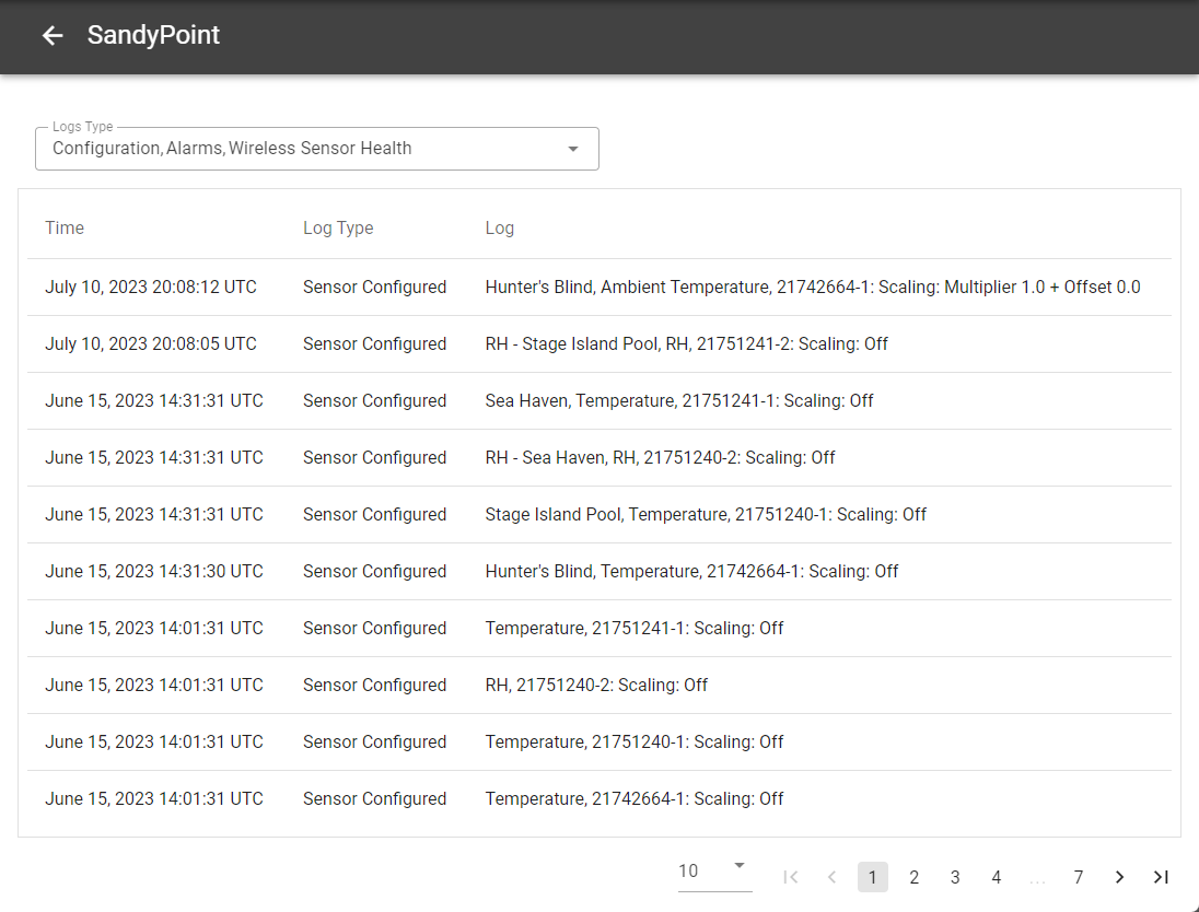
View logs
Logs tell you detailed information about the events for your device including information about connections, configuration, alarms and wireless sensor health.
To view the log:
-
Select Devices.
-
Select the station your sensors or modules are connected to.
-
Click Logs in the upper right corner of the page.
-
Use the Logs Type menu to select from among the available options.
The following shows a log of only the configuration events:
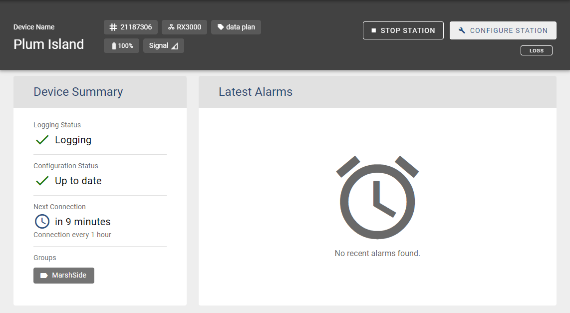
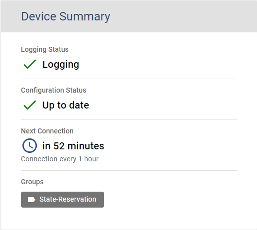
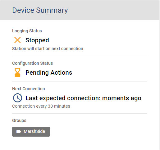
Device summary
The Device Summary displays what's happening with the device. The following images show two different summaries.
| Field | Description |
|---|---|
| Logging Status | The current status of the device. |
| Configuration Status | The state of the device's configuration. Also indicates there are pending changes that will be applied at the next connection. |
| Next Connection | The next time the device is expected to connect to LI-COR Cloud or other information about the connection. |
| Groups | The Groups the device belongs to. |
| Firmware Versions | Device's current firmware version. The Upgrade button appears when there is a new version available. Click Upgrade to review release notes and decide whether or not to apply the upgrade on the next connection. |
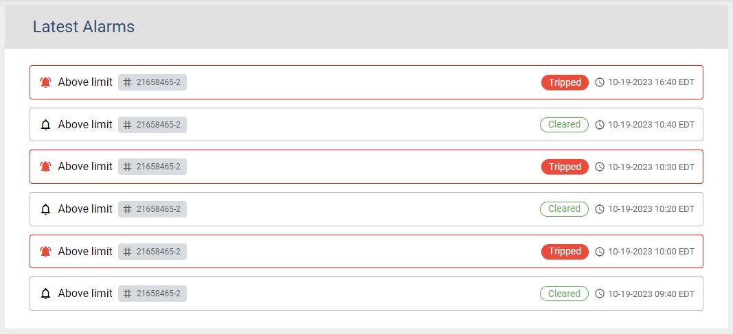
Latest alarms
The Latest Alarms section of the page displays a list of alarms and their causes, date and time of the alarm, and status.
Measurements
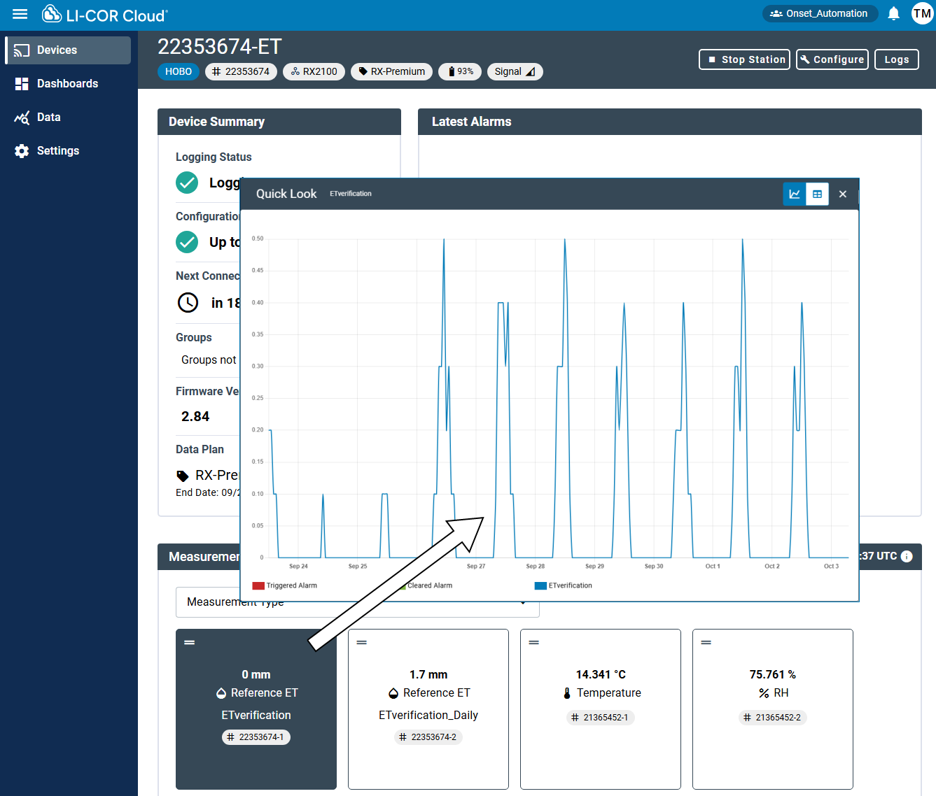
The Measurement section of the page displays a tile for each measurement reported by the station. Each tile displays the latest reading for that sensor, the type of measurement it is collecting (temperature, rainfall, and so on), a custom label that you can edit, and a serial number.
Note: Measurement tiles for wireless sensors display the latest date and time for the data they display. You can filter the list of sensors and move the tiles to a desired position in the interface.
Click any of the measurement tiles to see recent data as a graph or table. The Quick Look allows you to see recent conditions without having to create a Dashboard.
Configuration reference
The following tables describe the fields on the configuration tabs.
General configuration
| Field | Status | Description |
|---|---|---|
| Device Name | Optional | A nickname for the device that lets you identify it more easily than a serial number. LI-COR Cloud uses the device name to identify the device and its related data. |
| Time Zone | Required |
Specifies the time zone that the station uses to records all data. If you edit the time zone after initial setup, keep these points in mind: Changes to the time zone are not reflected in the device graphs until the next time the device connects with LI-COR Cloud. When you change the time zone for a device, double-check the Power Saving Mode settings (see Connection interval) to ensure the start and end time are still set correctly. |
| Group | Optional | Groups help you organize your devices. For example, you may have a group of devices that are geographically close. It may be helpful to give them all the same Group name. |
| Units | Required | All data that the station collects uses the unit you select. Choose from US and SI. |
Connection interval
Smart sensors logging
| Field | Status | Description |
|---|---|---|
| Logging Interval | Required | Sets frequency of data logging for all smart sensors. |
| Enable Sampling | Optional | This setting determines how often your sensor takes samples. The Logging Interval must be divisible by the Sampling Interval. When you configure a Sampling Interval, the station takes multiple measurements within a given Logging Interval and averages them together to create a single logged data point. |
| Sensor Configuration (available for each measurement the sensor collects.) | ||
| Label | Optional | Allows you to identify a measurement throughout the system with a custom label. If you do not enter a Label, LI-COR Cloud uses the sensor serial number. |
| Enable scaling | Optional | Scaling allows you to configure a sensor to scale logged data to a different unit than its default unit. It allows you to change to a different measurement type, different units, or to apply a multiplier or offset. See Scaling sensor data to learn more about the Scaling settings. |
Wireless sensors logging
| Field | Required/Optional | Description |
|---|---|---|
| Logging Interval | Required | This setting sets frequency of data logging for all wireless sensors. |
| Wireless Sensors Configuration | ||
| Wireless Sensors Label | Optional | This Label applies to the sensor itself and is used for maps and wireless sensor health. |
| Sensor Configuration (available for each measurement the sensor collects.) | ||
| Label | Optional | Allows you to identify a measurement throughout the system with a custom label. If you do not enter a Label, LI-COR Cloud uses the sensor serial number. |
| Enable scaling | Optional | Scaling allows you to configure a sensor to scale logged data to a different unit than its default unit. It allows you to change to a different measurement type, different units, or to apply a multiplier or offset. See Scaling sensor data to learn more about the Scaling settings. |
Analog sensors logging
| Field | Status | Description |
|---|---|---|
| Logging Interval | Required | This setting sets frequency of data logging for all analog sensors. |
| Sampling Interval | Optional | This setting determines how often your sensor takes samples. The Logging Interval must be divisible by the Sampling Interval. When you configure a Sampling Interval, the station takes multiple measurements within a given Logging Interval and averages them together to create a single logged data point. |
| Statistics | You must select at least one statistical measurement if you select Sampling Interval. | Statistics are calculated between each logging interval at the sampling interval rate you select. Each statistic value is then logged at each logging interval. Select the statistics to be logged: minimum, maximum, average, and standard deviation. |
| Excitation Power | Optional | Turns excitation on. |
| Warm up | Optional | With Warmup, the device supplies excitation power for a brief period prior to each measurement. This allows you to select the minimum warm-up time needed to allow for sensor stabilization while conserving battery power. For example, if you specify a warm-up of one second and set the logging interval for the module to one minute, the device powers the external sensor for one second, logs a measurement, and then turns off the excitation power for the next 59 seconds. Note that the excitation mode is automatically set to Continuous if the warmup time selected is within one second of or greater than the logging or sampling intervals. |
| Continuous | Optional | The device supplies constant excitation power to the sensor for the entire duration of the deployment. Continuous mode is required if the sensor needs more than two minutes of warm-up time. Continuous mode greatly affects battery life and is generally not recommended. |
| Sensor Configuration (available for each measurement the sensor collects.) | ||
| Enable channel | Optional | Select to turn on this channel. |
| Label | Optional | Labels help you organize your devices into groups. For example, you may have a group of devices that are geographically close. It may be helpful to give them all the same Label. |
|
Sensor/ Input Type |
Required if the channel is enabled | Specifies the type of input for this channel. |
| Enable Scaling | Optional | Scaling allows you to configure a sensor to scale logged data to a different unit than its default unit. It allows you to change to a different measurement type, different units, or to apply a multiplier or offset. See Scaling sensor data to learn more about the Scaling settings. The Scaling Settings displayed depend on the Sensor/Input Type you select. |
Relay modules
| Field | Status | Description |
|---|---|---|
| Label | Optional | Shows what Open or Closed corresponds to in your system (for example, "closed relay turns pump on"). |
| Normal Relay State |
Optional | Determines the state of the relay: Open or Closed. |
| On Next Connection | Optional | Determines the state of the relay the next time it connects to LI-COR Cloud. |
Water level sensors logging
| Field | Status | Description |
|---|---|---|
| Logging Interval | Required | This setting sets frequency of data logging for all water level sensors. |
| Sampling Interval | Optional | This setting determines how often your sensor takes samples. The Logging Interval must be divisible by the Sampling Interval. When you configure a Sampling Interval, the station takes multiple measurements within a given Logging Interval and averages them together to create a single logged data point. |
| Sensor Configuration (available for each measurement the sensor collects.) | ||
| Label | Optional | Allows you to identify a measurement throughout the system with a custom label. If you do not enter a Label, LI-COR Cloud uses the sensor serial number. |
| Enable Scaling | Optional | Scaling allows you to configure a sensor to scale logged data to a different unit than its default unit. It allows you to change to a different measurement type, different units, or to apply a multiplier or offset. See Scaling sensor data to learn more about the Scaling settings. The Scaling Settings displayed depend on the Sensor/Input Type you select. |
| Water Level | ||
| Measured Value | Required | Specifies the measured value of the water level. |
| Units | Required | Specifies metric or imperial measurement system. |
| Taken At | Required | Specifies the date and time of the measurement. |
| Water Density | Required | Specifies the density of the water by what type of water it is. |
FAQs: RXW-WL water level channel updates
Note: This information applies to RXW-WL deployments created before March 18, 2026. Deployments created after this date already use the updated channel structure and will not require dashboard or export updates.
After the recent LI-COR Cloud update, LI-COR Cloud created a new export channel for the updated RXW-WL measurement. Historical data remains available, and new data continues in the updated channel.
Dashboards referencing the previous channel may show only historical data. Add the updated channel to display current measurements.
In many cases, yes. Including both the previous and updated channel allows you to visualize the full record of historical and current data.
No. Existing scaling, offsets, and labels remain unchanged.
This change applies only to HOBOnet Water Level sensors (RXW-WL) used with RX stations in LI-COR Cloud.